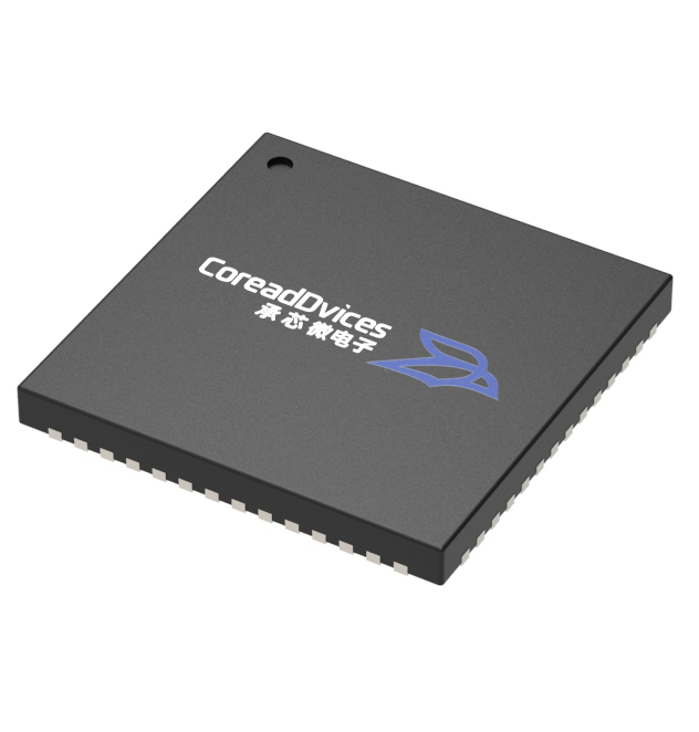
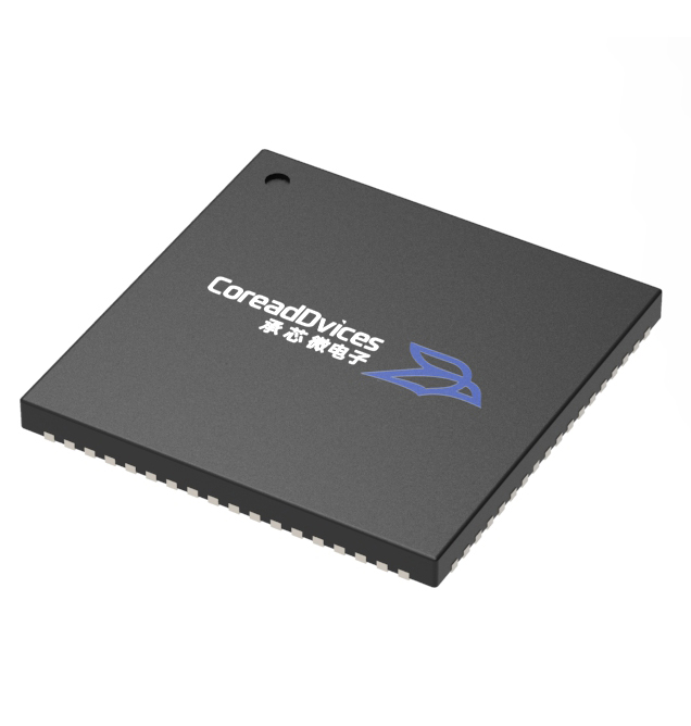
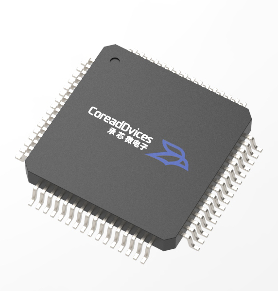
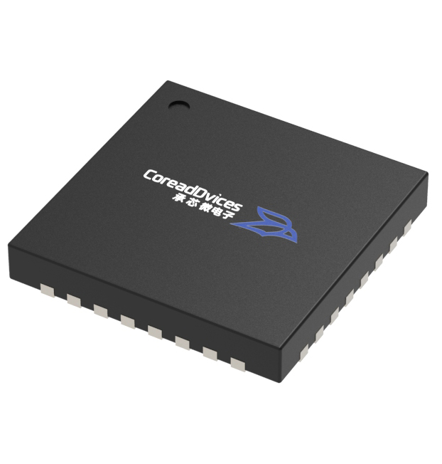

RS-485 is widely used in various communication scenarios, including industrial field applications and smart buildings. In practical deployments, long-distance transmission, high-speed communication, complex bus environments, and external electrostatic interference can all pose challenges to communication stability: long transmission distances and high communication rates may lead to signal quality issues; external electrostatic surges can adversely affect communication interfaces; and in cases of an open bus or an uncertain input state, abnormal output behavior at the receiving end may also occur.
These issues correspond, respectively, to interface design challenges such as signal integrity, ESD robustness, and deterministic receiver input state.
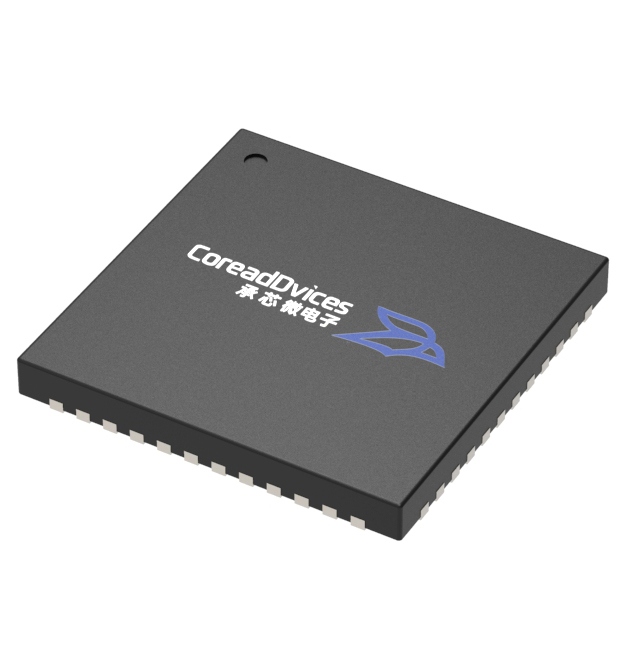
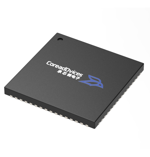
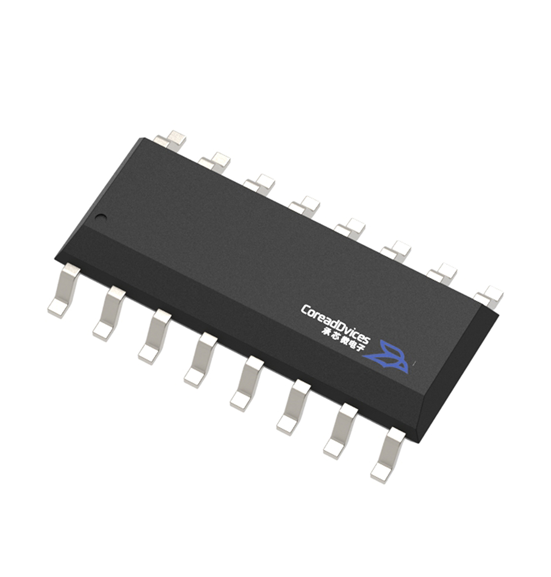
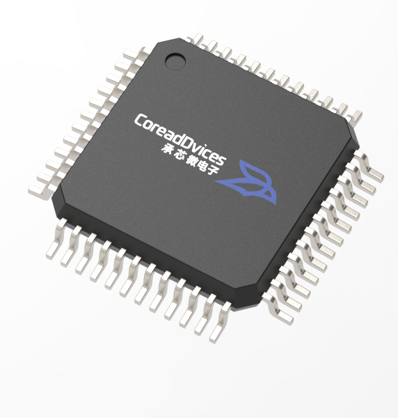
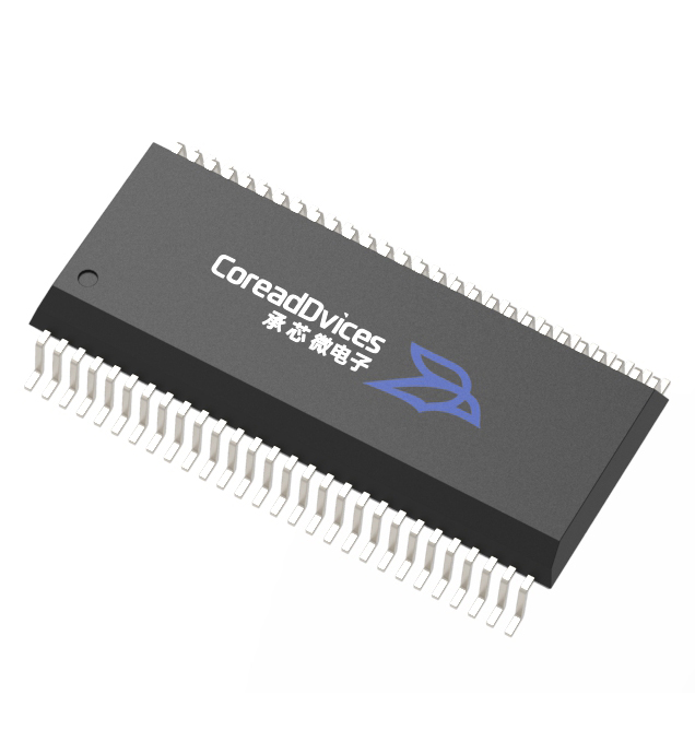
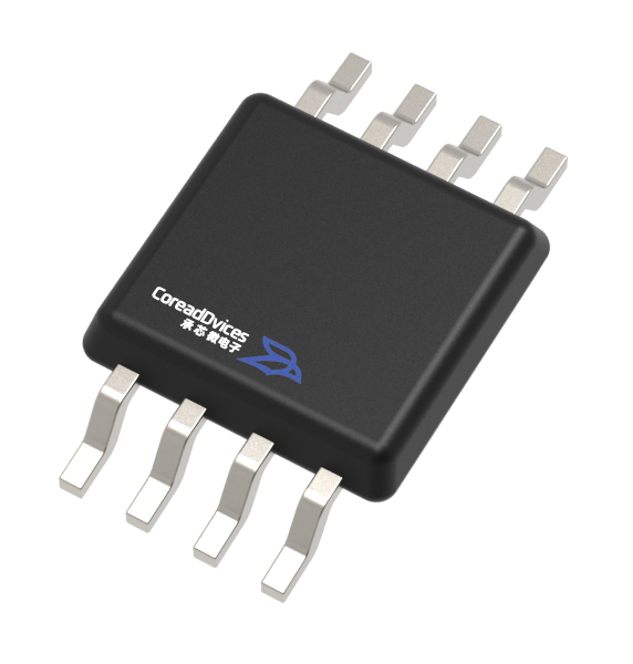
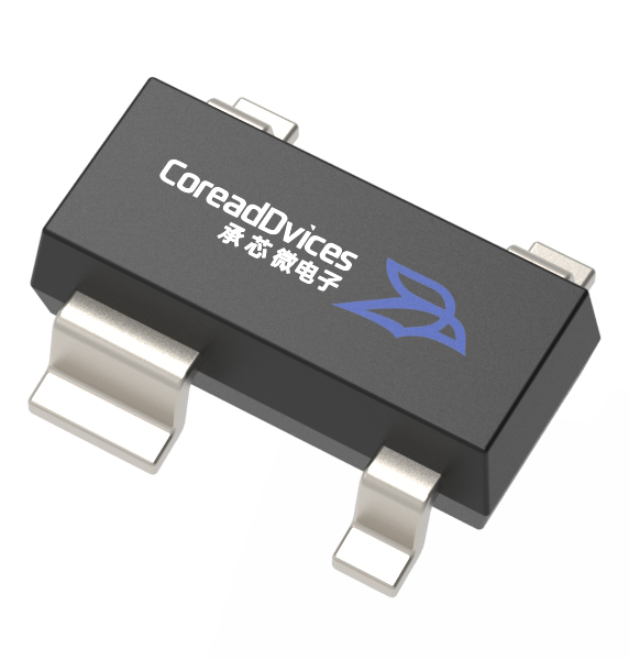
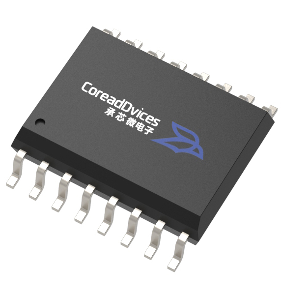
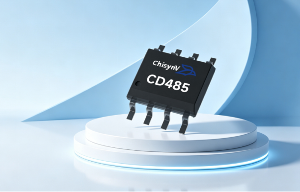
The CD485 is a low-power RS-485/RS-422 transceiver integrating a driver and a receiver, supporting a maximum data transmission rate of 10 Mbps. It features a wide common-mode input range, failure protection, current limiting, and overtemperature protection, providing appropriate interface performance support for typical RS-485 communication application scenarios.
What are the underlying causes of these three phenomena?
Long-distance signal reflection and terminal mismatch are among the typical causes of high-bit-error rates in high-speed communication systems. The characteristic impedance of an RS-485 twisted-pair cable is approximately 120 Ω; if no termination resistors are connected at both ends of the bus, signals will reflect at the terminations and superimpose onto subsequent code symbols. The higher the transmission rate, the more pronounced this reflection becomes, causing the eye diagram to collapse, the decision margin to be completely eroded, and, in the case of excessively long branches, the formation of stub lines on the main bus, which further degrades the signal waveform. Additionally, the potential difference across nodes combined with strong electrical coupling can push the common-mode voltage beyond permissible limits. Both inter-node potential differences and interference introduced by strong electrical environments may alter the common-mode voltage of the bus. Once this voltage exceeds the common-mode input range of the receiver, the decision of differential signals can be compromised—a phenomenon that often varies with operational conditions, such as the startup or shutdown of field devices. When the bus is open-circuited or in an idle state, the differential voltage levels become uncertain, which can cause the receiver to flip randomly. In the absence of a well-defined bias between nodes A and B, the differential voltage may fall near the threshold level or even remain in an undefined state; under such conditions, noise can be mistaken for valid data, leading to erratic bus activity.
CD485 Four-Level Protection Mechanism
1. Wide common-mode input range + input hysteresis
The receiver supports a wide common-mode input range from −7 V to +12 V, while also featuring 70 mV of input hysteresis. The wide common-mode input range provides greater common-mode operating margin for bus communications where node potential differences exist; the 70 mV input hysteresis reduces the likelihood of repeated logic state flips in response to minor disturbances to the input signal near the threshold level.
For communication systems in industrial field environments, where the electrical conditions are relatively complex, these two parameters can provide support for communication stability at the receiver signal decision level.
2. Fail-Safe Failure Protection
When the A and B bus inputs are in an open-circuit state, the RO output of the CD485 receiver remains at a high level. This ensures that even if no valid differential signals are currently present on the bus, the receiver will not exhibit random logic states due to the open-circuit input condition.
3. Return current limiting + overheat protection
The CD485 features a reverse current limiting mechanism and an overtemperature protection mechanism. In the event of abnormal conditions, such as a short circuit at the output, the reverse current limiting mechanism provides protection against excessive output currents; when the chip temperature exceeds a safe threshold, the overtemperature protection mechanism causes the driver to enter a high-impedance state.
4. ESD Protection
The CD485 exhibits high ESD tolerance, meeting the ±15 kV air discharge and ±8 kV contact discharge requirements of the IEC61000-4-2 standard; its A, B, Y, and Z pins also comply with the 15 kV HBM human body discharge test specification.
For RS-485 interfaces directly connected to external communication lines, ESD tolerance is a critical metric in interface reliability design, providing essential performance support for the communication interface when subjected to transient surges such as electrostatic discharge.
Overview of Key Parameters and Specifications
|
Parameter items |
CD485 metric |
|
interface type |
RS-485 / RS-422 |
|
working voltage |
4.75V–5.25V,5V single-power supply |
|
Maximum data transfer rate |
10 Mbps, no drive rate limit |
|
supply currentICC |
DE=0V: Typical 300µA / Maximum 500µA; DE=VCC: Typical 500µA / Maximum 900µA |
|
Common-mode input range |
−7V~+12V |
|
Differential threshold voltage |
−0.2V~+0.2V |
|
Input hysteresis |
70mV |
|
input resistance |
12kΩ |
|
Drive transmission latency |
Typical: 55 ns / Maximum: 60 ns |
|
Drive deviation |
Typical: 5 ns / Maximum: 10 ns |
|
Connectivity capability |
Up to 32 receivers on the bus |
|
Drive Protection |
Return current limiting + overheat protection |
|
IEC61000-4-2 |
±15 kV air discharge / ±8 kV contact discharge |
|
HBM |
Pins A, B, Y, and Z: 15 kV |
|
operating temperature range |
−40℃~+125℃ |
|
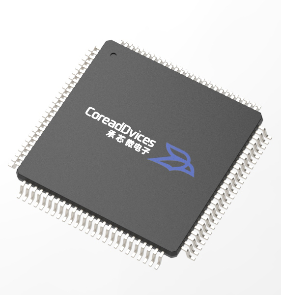
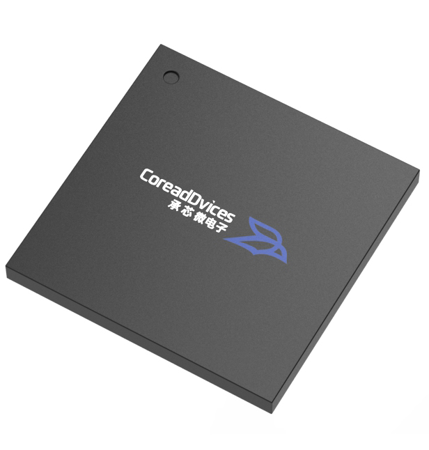
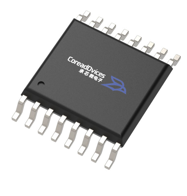
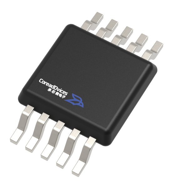
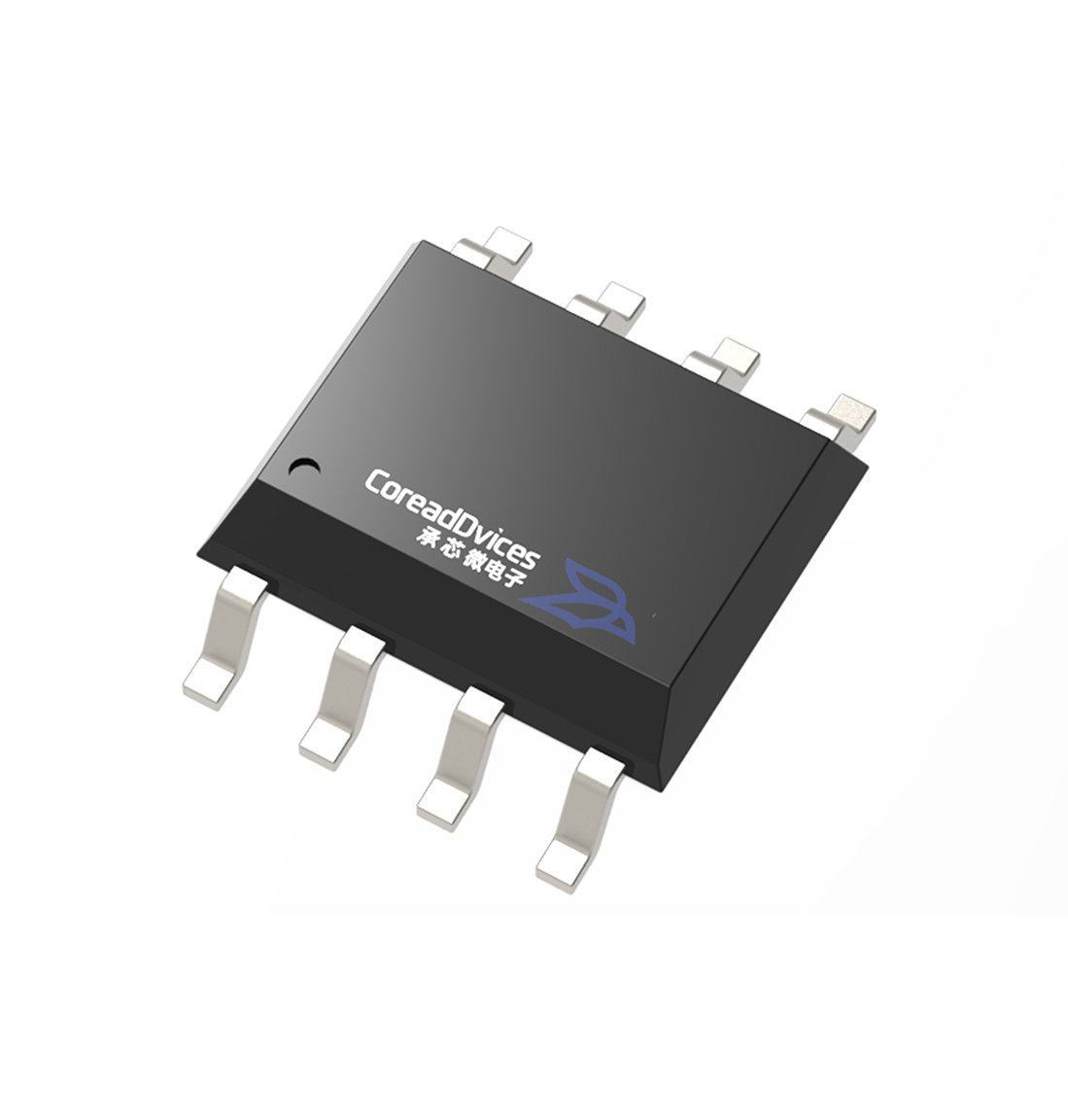
Packaging form |
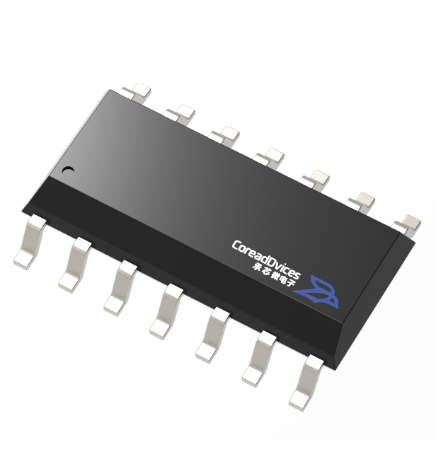
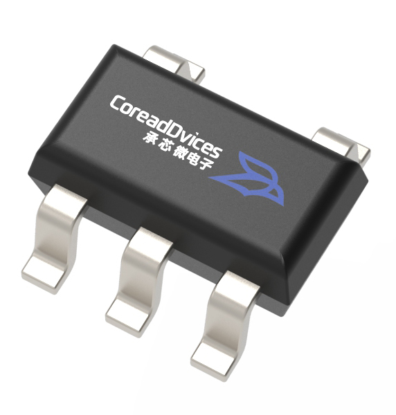
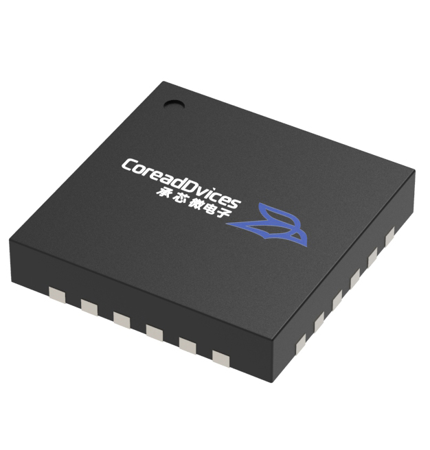
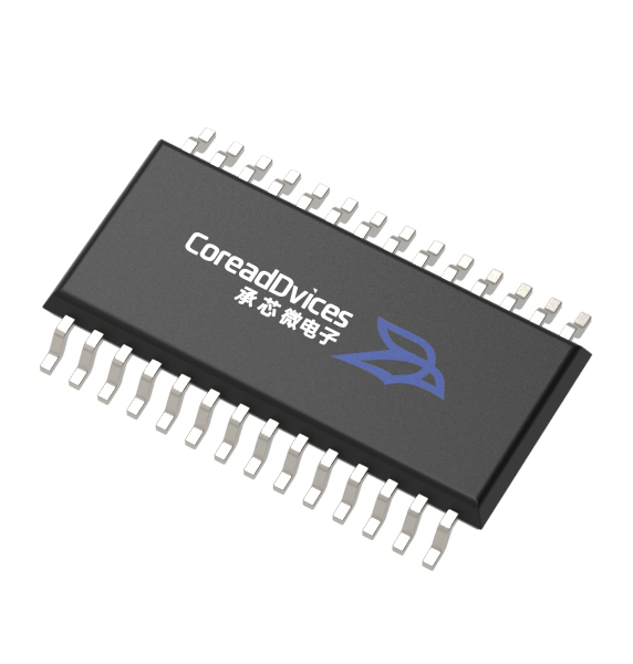
SOP-8 / MSOP-8 |
Typical Application Areas
1. Low-power RS-485 system: Featuring a low quiescent current of 300 μA, it is ideal for RS-485 communication systems where power consumption is critical.
2. DTE/DCE Interface: A standard differential interface device for communication between a data terminal equipment and a data communication device.
3. Packet switching: Supports high-speed differential data transmission and is compatible with packet-switched communication devices.
4. Local Area Networks (LANs): Suitable for multi-point data communication within local area networks.
5. Multi-channel data converter: Used for signal transmission and bus interfacing in multi-channel data conversion equipment.
6. Data Aggregation: Supports applications for multi-node data acquisition and centralized upload, leveraging the advantages of a multi-point bus architecture.
7. Integrated Services Digital Network (ISDN): Can be used for differential communication links in ISDN equipment.
Considerations for Engineering Applications
To fully leverage the performance of the chip, the following key considerations should be observed in hardware design:
Bus termination: In RS-485 bus design, terminal matching should be performed based on line characteristics and bus topology. To minimize reflections, the bus terminals should be appropriately configured, and the remaining segment at the junction between the transceiver and the main bus line should be kept as short as possible.
Direction switching timing: In a half-duplex RS-485 system, DE/RE direction switching must be properly controlled in accordance with the communication protocol. After transmission is complete, it is essential to ensure that the driver exits the active drive state before switching to the receive direction; in multi-node communication scenarios, care must also be taken to avoid simultaneous bus driving by different nodes, which could lead to conflicts.
Evaluate external protection based on the system environment: CD485 possesses the specified level of ESD tolerance; however, different systems may be exposed to different types of transient or external electrical environments. For outdoor applications or other scenarios involving more severe electrical stresses, it should be assessed whether additional external protection measures are required based on the actual system requirements.
The CD485 is a domestically developed transceiver designed for low-power RS-485 systems, multi-point data communication, data aggregation, and related RS-485/RS-422 interface applications, offering a solution that balances high-speed transmission, low power consumption, and robust interface protection capabilities.